1. Problem Statement
In this tutorial we are going to create a project to simulate a traffic light using arduino UNO R3 where the system will change from red to green, via amber and repeat this process again and again.2. What is a LED
A light-emitting diode (LED) is a two-lead semiconductor light source that resembles a basic pn-junction diode, except that an LED also emits light.An LED is a diode that also emits light. LEDs come in different colors and brightnesses, and can also emit light in the ultraviolet and infrared parts of the spectrum (as in the LEDs in your TV remote control). If you look carefully at an LED, you will notice two things. One is that the legs are of different lengths, and also, that on one side of the LED it is flattened rather than cylindrical (see Figure). These are indicators to show you which leg is the anode (positive) and which is the cathode (negative). The longer leg (anode) gets connected to the positive supply (3.3V) and the leg with the flattened side (cathode) goes to ground.

There is another LED called RGB LED which has a red, green, and blue one package. The LED has four legs: one will be a common anode or cathode, common to all three LEDs and the other three will then go to the anode or cathode of the individual red, green and blue LEDs. You can get any color you want just adjusting the brightness values of the R, G and B channels of the RGB LED.
3. Parts Required for Traffic Light
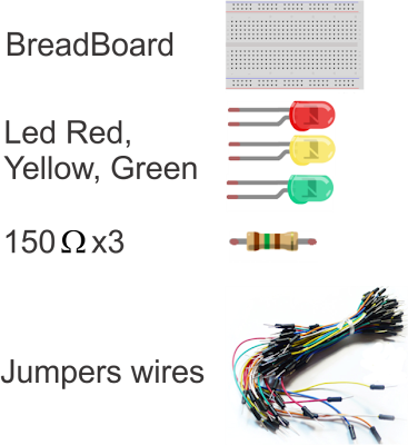
for implement this project we will need the following materials, breadboard, 3 LEDs(Red, Yellow and Green), 150ohm resistors(3) and jumpers wires to connect.
4. Sketch for Traffic Light
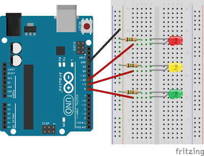
Using Fritzing we draw the following sketch for traffic light project, we just need to make some simple connection as we can see in the next figure.
5. Coding traffic light
In this section we need to write some code for making run our traffic light project just type the following code in the text area of arduino editor. Make sure your arduino is not connected to computer while you assemble the project to avoid damage to the board.
//Traffic light in arduino UNO R3
int ledDelay = 10000; // delay in between changes
int redPin = 10;
int yellowPin = 9;
int bluePin = 8;
void setup() {
  pinMode(redPin, OUTPUT);
  pinMode(yellowPin, OUTPUT);
  pinMode(bluePin, OUTPUT);
}
void loop() {
  digitalWrite(redPin, HIGH); // turn the red light on
  delay(ledDelay); // wait 5 seconds

  digitalWrite(yellowPin, HIGH); // turn on yellow
  delay(2000); // wait 2 seconds

  digitalWrite(bluePin, HIGH); // turn green on
  digitalWrite(redPin, LOW); // turn red off
  digitalWrite(yellowPin, LOW); // turn yellow off
  delay(ledDelay); // wait ledDelay milliseconds

  digitalWrite(yellowPin, HIGH); // turn yellow on
  digitalWrite(bluePin, LOW); // turn green off
  delay(2000); // wait 2 seconds
  digitalWrite(yellowPin, LOW); // turn yellow off
  // now our loop repeats
}
Finally verify if there is not error and connect the arduino USB to your computer and then press in Upload Icon to run.You can see video demonstration on YouTube.
Hello;
ReplyDeleteI am new in this field i need a simple single LED flasher/Solid circuit that accepts 3 types of input signal from a circuit one is positive +5v to gnd and other is -5v to gnd when +5 signal input to arduino it should solid ON and when -5v signal input the LED starts flashing LED at rate of 2sec and when no signal (below 2v) LED off.Please reply at faizan.hamayun@hotmail.com